An FR-4 plant is not a collection of machines. It is a material-conversion system in which resin chemistry, glass-cloth handling, B-stage control, layup discipline, press scheduling, utilities and quality assurance must all operate at the same production rate.
That distinction matters. A factory can own a fast impregnation line and a large press yet still miss its output target because the resin kitchen cannot feed stable batches, the layup room cannot prepare books fast enough, the cold press becomes the scheduling constraint, or the product mix creates more press occupancy than the original capacity estimate assumed.
A sound full-plant design therefore starts with the product and the production model—not with a machine catalogue.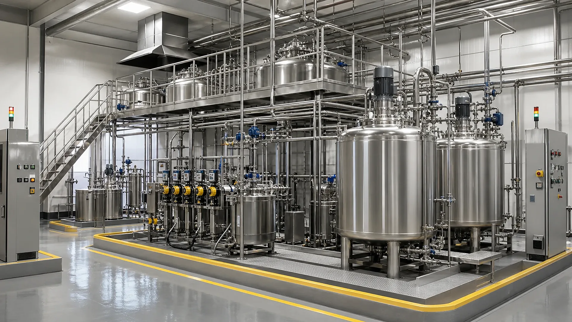
Figure 1. Resin kitchen
FR-4 is a glass-cloth-reinforced epoxy laminate grade. For industrial electrical insulation sheets, the finished product is normally an unclad rigid laminate. Copper-clad laminate (CCL) uses a related prepreg and pressing route but adds copper foil, different surface requirements and, depending on the intended electronics application, additional process and cleanliness demands.
Before equipment is sized, the project team must lock down:
IEC 60893 covers industrial rigid laminated sheets for electrical purposes and includes epoxy binders and glass-cloth reinforcement. NEMA’s industrial laminate standards and customer-specific requirements may also apply. A flammability designation or claim must be supported by the relevant tested construction; “FR-4” should not be treated as a substitute for a product-specific UL 94 result.
The resin kitchen converts purchased chemicals into a repeatable impregnation resin. Its design must control formulation accuracy, mixing sequence, temperature, viscosity, solids, filtration, storage time and delivery to the impregnation line.
A practical resin-preparation area may include:
The correct vessel count is not selected by copying a previous project. It depends on batch size, mixing time, testing and release time, transfer time, cleaning/changeover time, resin pot life, line consumption and the amount of production buffer allowed.
A useful design relationship is:
required mixed-resin supply rate = dry-glass throughput × resin-to-glass ratio ÷ process yield
The kitchen must then be checked dynamically: can one batch be mixed, tested and released before the active service tank reaches its minimum operating level? If not, the solution may require larger batches, parallel preparation, additional day-tank capacity, faster release testing, or a different campaign strategy.
This is the first capacity anchor. An impregnation line advertised at a particular mechanical speed has no value if the resin kitchen cannot supply stable resin at the corresponding mass flow.
The vertical impregnation line performs four connected tasks:
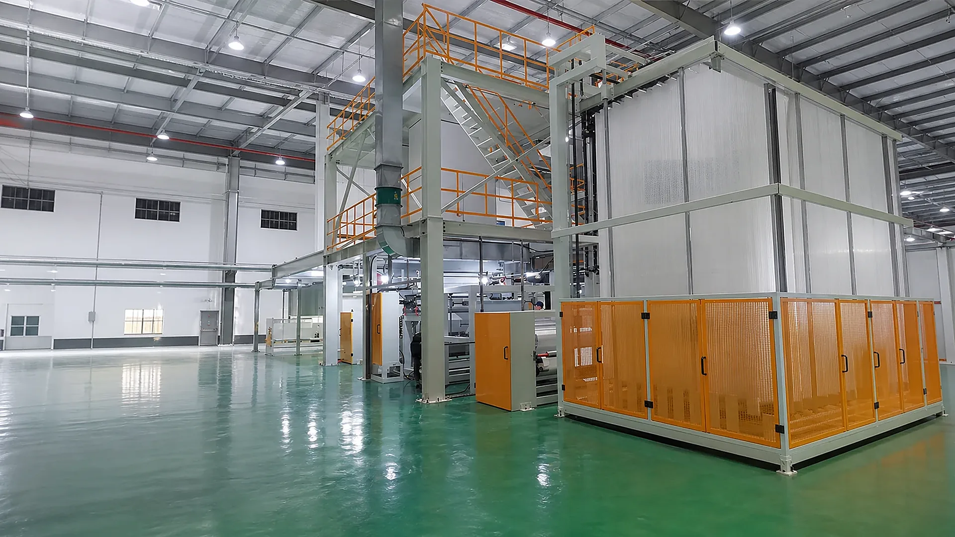
Figure 2. Vertical impregnation and drying line
Critical design variables include:
The oven is usually the real process constraint. Line capacity cannot be calculated from speed and width alone; the selected resin, cloth, pickup, volatile load and B-stage window determine whether that speed is technically usable.
For preliminary planning:
dry-glass throughput = usable width × operating speed × glass areal weight × uptime
and:
prepreg throughput = dry-glass throughput ÷ glass mass fraction in the prepreg
These equations establish a mass balance, not a guaranteed production rate. A qualified design must apply product-specific recipes, trim, splice losses, start-up waste, changeovers, downtime and inspection yield.
The exhaust-treatment concept must be designed from the actual formulation and solvent mass balance. Oven air, heat recovery, thermal-oil duty and abatement equipment are connected design decisions; they should not be purchased as independent packages.
Prepreg continues to change after it leaves the dryer. Its handling route should minimize contamination, uncontrolled heat exposure, moisture uptake, blocking, edge damage and traceability loss.
The plant layout should define:
This buffer must be large enough to decouple normal process variation, but not so large that excess work-in-process hides quality problems or consumes shelf life.
Layup determines the laminate construction. Operators or automation assemble the required number and sequence of prepreg sheets between clean press plates and release materials. After pressing and cooling, laydown separates the laminate from plates and process materials for downstream finishing.
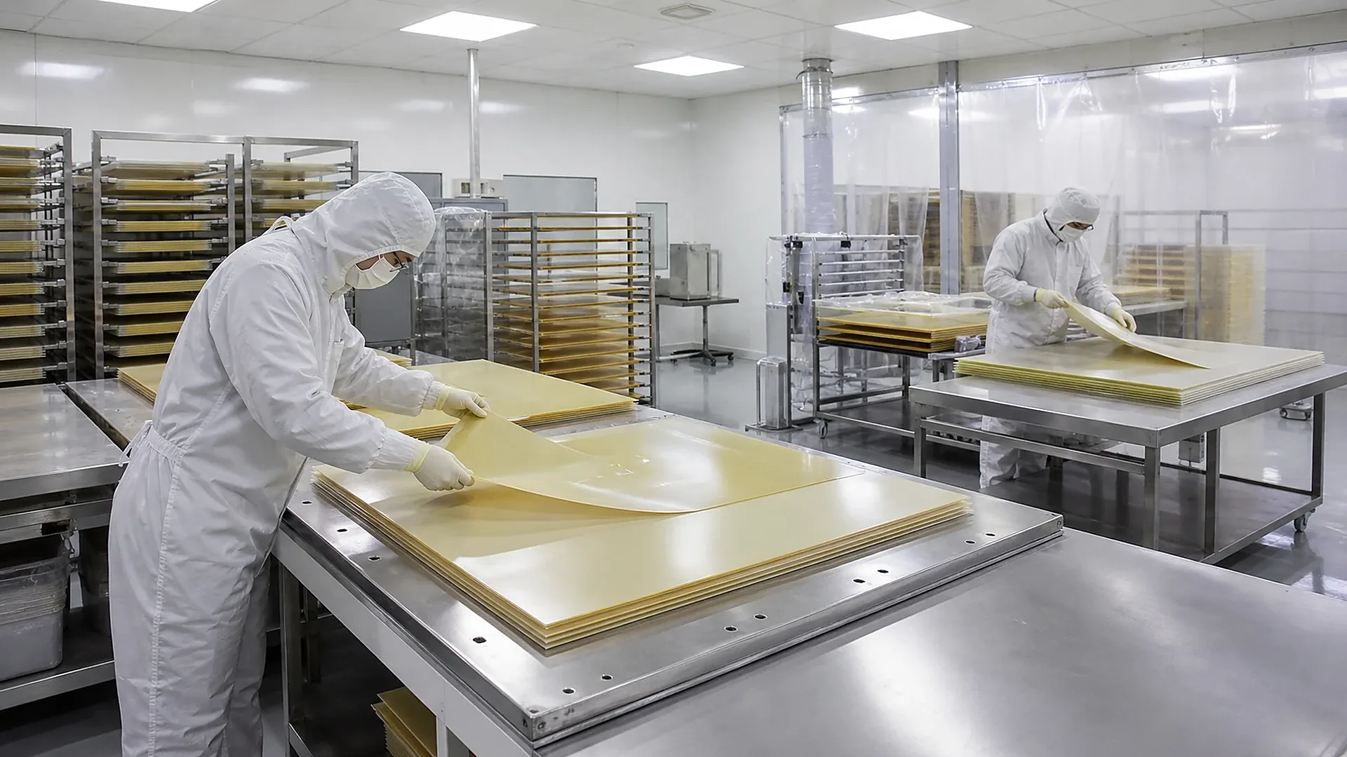
Figure 3. Layup & laydown
The room and handling system must protect:
Layup capacity should be calculated in books per hour and sheets per hour for the real product mix. A thick sheet may require many prepreg plies but produce fewer finished sheets per book; a thin sheet may increase handling count and plate demand. Manual, semi-automatic and automatic systems therefore need to be compared by construction complexity and changeover pattern—not by a generic cycle time.
Plate washing, inspection, handling and return are part of the same loop. A press cannot run if clean plates are not available at the required rate.
A 2H1C system uses two hot presses and one cold press. The hot presses execute the programmed heat-and-pressure cure; the cold press cools the completed books under controlled pressure before laydown.
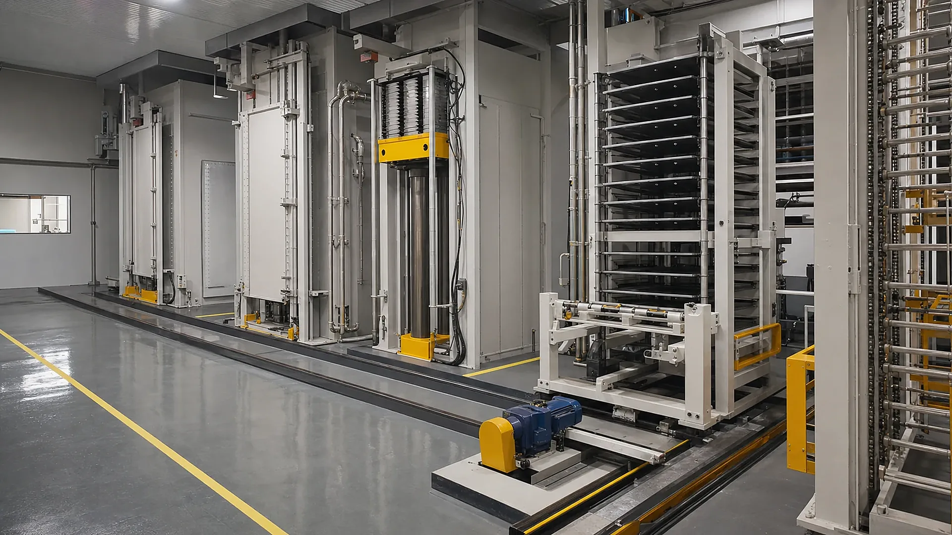
Figure 4. 2H1C press system
Separating heating and cooling can improve thermal efficiency and equipment utilization because the hot presses do not need to perform a full cooling stage for every load. But “two hot, one cold” is not a universal answer. It works only when the press-cycle balance supports it.
The fundamental scheduling test is:
required cold-press service rate ≥ combined discharge rate of the two hot presses
In simplified form, the relationship between hot occupancy and cold occupancy indicates whether one cold press can support two hot presses. The complete calculation must include:
Press force must be derived from required specific pressure and effective pressing area:
total press force = required specific pressure × effective loaded area × design allowance
This is why nominal tonnage alone is not an adequate press specification. Platen size, pressure uniformity, frame deflection, daylight count, opening, temperature uniformity, vacuum performance, hydraulic control and the loading pattern all affect the result.
The 2H1C area also requires a coordinated material-handling concept: loading station, transfer car or rail system, hot presses, cold press, unloading/laydown interface, hydraulic systems, thermal-oil system, cooling-water system, vacuum system, controls and safety interlocks.
After laydown, the exact route depends on the product specification. Typical operations can include:
Quality control should be designed as a traceability chain:
raw material lot → resin batch → prepreg roll/sheet lot → layup construction → press cycle → finished sheet lot → test record
This makes troubleshooting faster and prevents a local defect from becoming an uncontrolled factory-wide problem.
FR-4 plant performance depends on stable utilities. The full design should account for:
A utility estimate based on installed motor nameplates is not enough. The plant must be modelled by operating state: start-up, normal production, simultaneous press cycles, product change, cleaning and emergency condition.
The final design should express capacity at several levels:
The governing plant output is the lowest sustainable output among the connected stages:
saleable plant capacity = minimum(stage capacities) × integrated yield
This is the hidden reason many catalogue-based projects underperform. Each major machine may appear large enough in isolation, yet the integrated line has no common product basis, no shared utilization assumption and no bottleneck test.
A credible proposal for machine quantity, vessel capacity, impregnation-line width and speed, press tonnage, platen size, daylight count and utility duty begins with a controlled project brief.
Prepare the following:
Matthew can then convert the requirement into a mass balance, press-cycle model, bottleneck map, preliminary equipment schedule and utility concept. That is the correct point to decide how many machines are required and what their capacities and parameters must be.
The best FR-4 plant is not the one with the largest press or the fastest advertised impregnation line. It is the plant in which:
If you are planning a new FR-4 insulation-sheet plant or expanding an existing line, consult Matthew with your product mix, target output and site conditions. The next step is a project-specific capacity model—not a generic machine list.


